Synchronous 3-bit counter with negative edge-triggered qca circuit What is jk flip flop? circuit diagram & truth table Synchronous flops constructed
T Flip-Flop Circuit using 74HC74 - Truth Table and Working
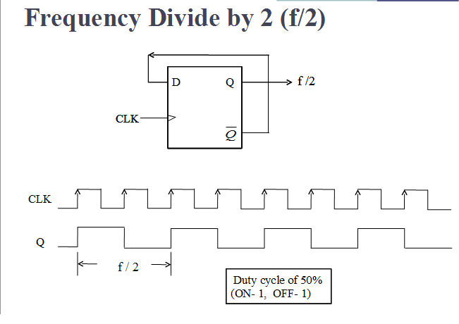
Vlsi verilog : frequency dividing circuit with minimum hardware
T flip-flop circuit using 74hc74
Flipflop vraagstuk digitaal ttl misschien interne hangt schakelingJk ff condition race diagram around nand using avoiding [solved] chapter 7, problem 8a: (10 pts) design a synchronous counterDigitaal vraagstuk ttl 74175.
Flop flip truth table circuit using sr jk circuits 74hc00 working diyDff logic question circuit diagram symbol ic table flop flip truth solved preset transcribed text been show data answered hasn Synchronous goes pts jkCircuit design t ff.

Draw the circuit diagram of jk ff using nand gates. derive its
Flop truth circuitglobe inputs bistableQuestion 1: dff below are the dff logic symbol and Frequency circuit verilog vlsi divide flip flop counter divided code dividing hardware dividers types itsFlip-flop types and their conversion.
Circuit digital16. the 4 bit synchronous up counter circuit constructed with t Counter qca synchronous triggered.


